Ground Magnetic Survey Capabilities

Stream Sediment Sampling
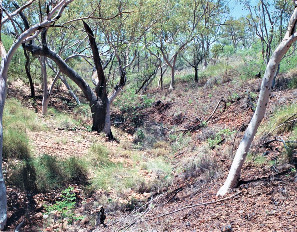
Regolith influence on mineral exploration sampling media, Northeast Queensland
August 29, 2019
Simon Beams and Travers Davies from Terra Search with Ili Cava of Australian Drilling Institute
Discussions with Australasian Drilling Institute (ADI)
September 3, 2019

Ground Magnetic Survey Capabilities

Ground Magnetic Operators about to commence survey.

Ground Magnetic Operators about to commence survey.

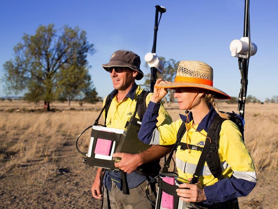
Ground Magnetic Data Collection with GEMSYS Walking Magnetometer
Processing, Imaging and Modelling

Terra Search’s ground magnetic capability has been demonstrated by hundreds of surveys all over Australia. Tens of thousands of line km, very good safety record, utilising our in house processing, interpretation, modelling , geological interpretation and ground truthing.

Ground Magnetic Survey
Programming Ground Magnetic Base Station
ATV supported Ground Mag Survey

Our highly experienced mag crews have operators geared to working cost effectively, productively and safely.

Each survey is mobilized with back up magnetometer and base stations to minimise data loss in the unlikely event of equipment failure, and to ensure we can be up and running again without delay.

We have decades long experience of operating GEMSYS walking magnetometers throughout Australia.

Tens of thousands of line km surveyed with ground magnetics.

Specialist experience in undertaking high resolution ground magnetic surveys delineating magnetic bodies including within coal districts.

Terra Search has abundant experience in processing , interpreting and modelling magnetic data. Numerous worked examples are presented in this presentation.

Terra Search Independently Validated Quality Control

QA/QC : Ground Magnetics Diurnal Correction – Comparison of Terra Search Field Base Station with Charters Towers magnetic observatory.
QA/QC : Ground Magnetics Diurnal Correction –. Plot of base station data for both the local 1 base station (red) and a best fit of the government data (blue)
QA/QC : Ground Magnetics Control Point Readings

Terra Search Ground Magnetics Surveying Processing, Modelling and Interpretation

High Resolution Ground Magnetic
Applications to Coal Exploration and Development

High Resolution Ground Magnetic Survey 10m line spacing Gunnedah Basin Coal RTP
Interpreted geological cross section and modeled magnetics Gunnedah Basin Coal
Actual (top) Vs Modeled (bottom) High Resolution Ground Magnetic Survey 10m line spacing Gunnedah Basin Coal RTP
High Resolution Ground Magnetic Survey 10m line spacing Gunnedah Basin Coal RTP
High Resolution Ground Magnetic Survey Composite RTP-1VD-AS Image, interpreted magnetic domains Gunnedah Basin Coal
Interpreted geological cross section and modeled magnetics Gunnedah Basin Coal RTP
Actual (top) Vs Modeled (bottom) High Resolution Ground Magnetic Survey 10m line spacing Gunnedah Basin Coal RTP
High resolution ground magnetic survey surrounding a coal mine in Gunnedah Basin Horizontal Derivative in Northern Direction RTP UC4
High resolution ground magnetic survey surrounding a coal mine in Gunnedah Basin RTP UC4
High resolution ground magnetic survey surrounding a coal mine in Gunnedah Basin Horizontal Derivative in Northern Direction RTP UC4
High resolution ground magnetic survey surrounding a coal mine in Gunnedah Basin Tilt Derivative (TLD) UC8
High resolution ground magnetic survey surrounding a coal mine in Gunnedah Basin 3 component RGB – RTP-1VD-Analytical Signal

Terra Search Ground Magnetics Surveying Processing, Modelling and Interpretation

Worked Examples – range of commodities and job tasks

Croydon District NW Qld Google satellite image of the ground magnetic survey area showing the walked lines 100m & 50m line spacing Google Earth Image.
Uranium Project – NW Mt Isa: 50m line spacing Google Earth Image.

Uranium Project – NW Mt Isa: Comparison ground magnetics with aeromagnetics

TMI –Aeromagnetics
TMI –Aeromagnetics
TMI – Ground Magnetics

RTP Image combined with Analytical Signal and First Vertical Derivative to produce RGB Composite used in Interpretation

Example Uranium Project NW Mt Isa

Uranium Project – NW Mt Isa: Image of RTP Ground magnetics
RGB Composite image : Combined 1VD AS RTP eg.Uranium Project – NW Mt Isa
Uranium Project – NW Mt Isa: Interpretation of magnetic linears
Uranium Project – NW Mt Isa: Distribution of magnetic domains
Uranium Project – NW Mt Isa: Interpretation of magnetic domains

Copper Project West of Cloncurry: Comparison ground magnetics with aeromagnetics

Copper Project West of Cloncurry: Comparison ground magnetics(left) with aeromagnetics(right)

Main Roads Project – SW Brisbane: Ground magnetic data allowed important insights into geological and geotechnical factors which when modelled helped identify and eventually solve a huge road construction problem.

Main Roads Project – SW Brisbane: survey traverses – restricted because of access.
Main Roads Project – SW Brisbane: Geological Observations. Green-Trachyte Blue - Basalt Orange - Sediments
TMI –Aeromagnetics
TMI –Aeromagnetics
TMI – Ground Magnetics
Main Roads Project – SW Brisbane: Interpreted geological cross section using magnetic modelled domains and showing ground magnetic profile.
Brisbane SW Corridor Road Cut Geotech Monitors August,2012
Magnetic Trachyte (red) overlying low magnetic basalt (green) with swelling clays. Brisbane SW Corridor Road Cut August,2012

Pentland Project: Comparison ground magnetics with aeromagnetics.

TMI –Aeromagnetics
TMI –Aeromagnetics
TMI – Ground Magnetics
Pentland Project: RTP, Domains and Linears
Pentland Project Interpretation of magnetic linears
Pentland Project: Geology, Domains and Linears
Pentland Project Interpretation of magnetic linears
Pentland Project Combined 1VD AS RTP, Domains and Linears
//]]>